
Resin patterns obtained in vacuum-sealed sand moulds |
|
5.2. Sand shooting The second point of the approach includes the wear research in conditions near to the real. It is used one of the most abrasive methods like shooting. In the same time, for wear augmentation, it shoots with one of the most abrasive materials like pure silica sand. Therefore here a minimum possible limit n of wear-resistance is determinated. The limit n is passed by all compounds compulsory and it would be defined as guaranteed wear-resistance. It does not require specifying of the composition of the moulding mixtures or the moulding method, so it has a definite universality. But, the guaranteed wear-resistance n makes sense when the comparison between the pattern materials is made. It will be of interest of patternmakers in giving of guarantee for their patterns in the exploitation. The wear test with sand shooting however is long, with a continuously engage of operator, and dangerous dust pollution. By reason of that, the wear of great number of pattern materials is unthinkable. Four samples are tested in the second point (Fig.31). Three of them are the representative compounds 1, 11 and 21. The fourth sample with compound 1' is made in a plastic mould. All samples are manufactured together in equal conditions with the samples used in the rotation and with these which will test in the third point of the study. The samples are fixed to a base and around them a plastic tube is disposed. The sand for shootings is the same as used in the rotation. The shooting (core) machine is KS-3 (Germany) and its working air pressure is 5.5-6.0x10⁵ Pa. The hole in the blow plate is completed with a labyrinth attachment for averting of sand outflow. The lessening of dimension A, mm, after results processing is presented in Fig.32. After 5000 shootings the extrapolation is made (up to -1.6 мм). 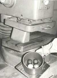 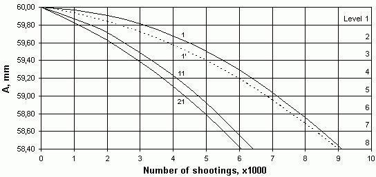 Fig.31 Fig.32 The samples before the shooting Wear in sand shooting, results for samples 1, 1', 11 and 21 Through interpolation of the results from Fig.32, the number of shootings in which the samples cross the eight levels is determinated (Table 6). By the multiplication of the coefficients K1-8 (Table 4) with the corresponding values of Table 6 is defined the guaranteed limit n of wear-resistance for the non-participated in the shooting compounds (Table 7). For example, for compound 2 and the first level, n12*1 = К12/1 . n11 , n12*1 = 0.750 x 3050 = 2287 , with the rounding to integer number. Table 6
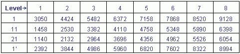 Table 7
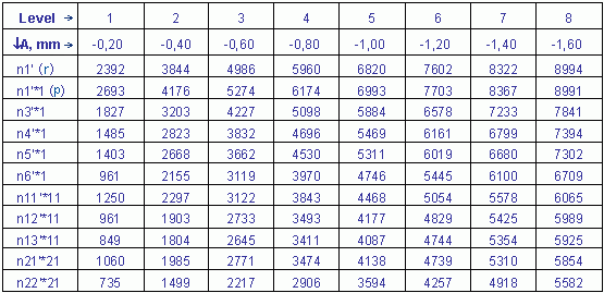
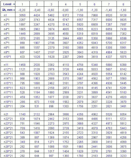 The determination of n for compounds (samples) from the conventional technology is made again by the multiplication of the coefficients K1-8 (Table 5) with the corresponding values of Table 6. The results are shown in Table 8. Except for the computed (prognosticated) wear-resistance of compound 1' : n1' *1(p), in Table 8 is inserted the relevant row from Table 6 for the real wear-resistance of the same compound n1'(r). Thus, it becomes possible to check the approach accuracy by the comparison between these values. Table 8
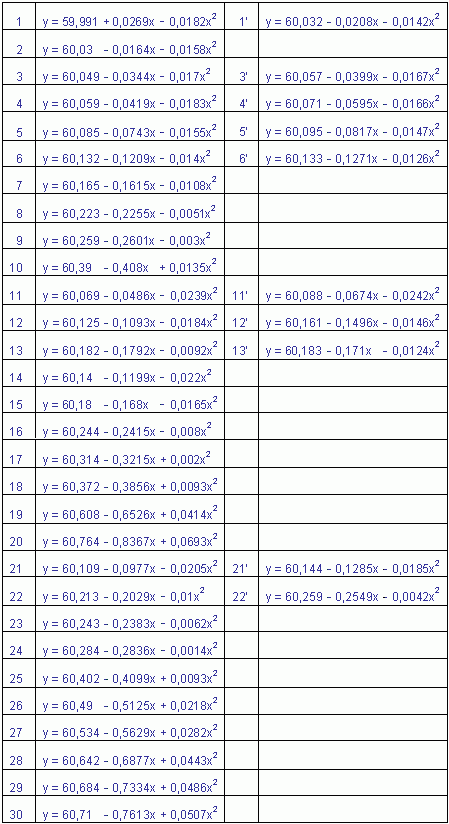
 As a result of regression analysis the equations for n are worked out (Table 9). Table 9
 « « « previous page next page » » » |