Resin patterns obtained in vacuum-sealed sand moulds |
|
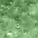
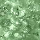
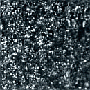
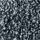
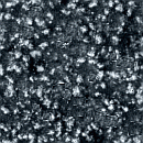
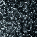
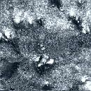
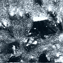
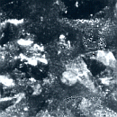
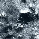
5.5. Visualization of the resin patterns wear The visual presentation of the resin patterns wear is based on the information from: - the structural analysis of the external layers of the samples made of epoxy resin AP1 and different kind of filler (Fig.37), and - the quantitative analysis [41,42] for the component distribution in the working surface (Fig.38). 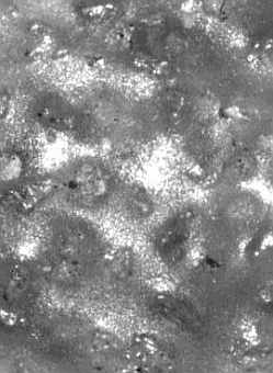
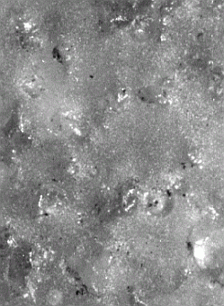
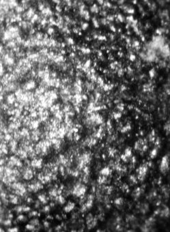
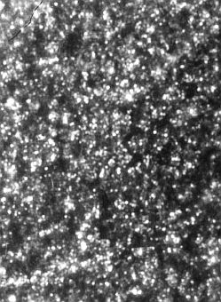
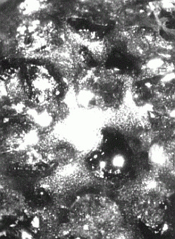
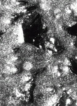
a) b) c) Fig.37. Some of pictures served for the analysis of the surface structure in the wear (x24) a) silica sand; b) Fe-dust; c) corundum; left-rounded top, right-wall of the sample. 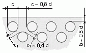
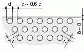
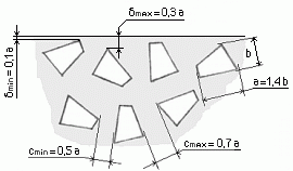
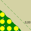
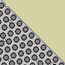
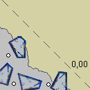
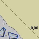
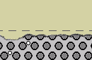
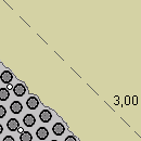
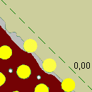
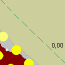
a) b) c) 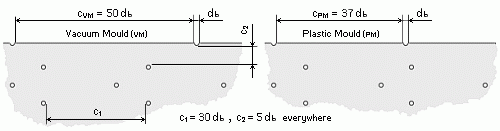 d) Fig.38. Distribution of the silica sand (a), Fe-dust (b), corundum (c), and air bubbles (d) in the epoxy resin The illustrating of the most important moments in the wear of resin patterns with sand filler (compound 21, Table 1) is realized with eight schemes (Fig.39). The first of them is related to the start condition of the surface. The other schemes show the process growth and they are bound with a dimension lessening, mm (left to right): 0.01-0.05, 0.06-0.10, 0.11-0.14, 0.15, 0.16-0.20, 0.21-0.24, and 0.25. For the covering of the whole interval 0.01-1.6 mm used in experiments (or any other interval), the same figures are used again, but with other value of the level. All that permits a very good synchronization with the values of the limit N. The figure columns are in combination with corresponding pictures of the structure (Fig.39). It is the similar in the illustrating of the wear of resin patterns with Fe-dust (compound 5, Table 1) - Fig.40, or corundum (compound 11, Table 1) - Fig.41.
Based on the illustrations above and additional microscopic examinations (x40) a brief description of the wear by shooting here is done. In start position, the most external layer consists of resin, independently of the fillers and the patternmaking technology. That is why, right from the start the sand flow begins actively to cut off the parts of the outmost resin. This process is more slow in working layers structured in the contact of the foil from the vacuum-sealed sand moulds. The obtained shine surface serves as a repulsive screen which does not permit sizable incising of sand grains into the resin. In the samples and patterns made by the conventional technology in plastic moulds, the peaks of their more roughness working layers are broken off and removed easily and fast. The bubbles on the surface expand quickly and because of their contiguity location to the filler, they undermine its particles. Many sand grains are impacted (wedged) in micropores, and stay there as call forth a microcracks. The presence of similar centers of destruction creates the most favourable circumstances for accelerated wear which is typical for a later period of abrasion for zones without defects. Gradually, a lots of filler fragments begin a direct opposition to the sand flow. The more quickly fillers take part in the interaction with the abrasive sand medium, the more the surface state stabilize for a long time and the wear becomes weak. That applies to the optimum prepared compounds, in which the filler is good packed with resin. That means that the resin is sufficiency for insurance of the strength of the connection between the filler particles, but not so much for the opening of big areas between them, where the resin fragments are cut off easily and the undermining of the filler grains goes. The sand flow repulsion by the harder grains of corundum (and carborundum) is fairly good. In use of metal fillers begins a process of plastic deformation of their grains. Alter the flattening by the sand flow, the metal grains hold comparatively favourable positions in the structure of the working layer and preserve the contiguous resin from the abrasive media. Further begins a gradually removal of the resin which connect the filler particles. For a different time it comes to state when the resin between the filler is eliminated, the filler becomes in bracket fixing and it is already possible the breaking out of whole grains or parts of them. The spherical form is more pliable to the entire elimination for the less contact area with the resin. The angular or fractured grain form predestines an inclination for breaking of parts, and more particularly in lapping of contiguous grains. It should be taken account of the brittleness of the hard materials too. The cutting of the deformed thin fragments of the metal filler together with the resin is already good expressed too. The breaking of one or more grains is facilitated strongly by the inside bubbles in every cases. The removed grains open empties and unevenness which accelerates the undermining of the contiguous grains. Independently of the kind of the filler, in fixed moment a whole its layer is expelled. The wear of the resin follows again, but in contrast to the start, the roughness is higher and the wear grows very fast. That intensity is kept to the opening of new layer of wear-resistant filler. These are the predominant situations in the resin patterns wear. In reality, the process contains a great number of intermediate and run together states, which accelerate or prevent the wear. A few samples here are shown which cover some other cases in the wear of the resin patterns. The schemes for the horizontal and sloping pattern walls (draft 1° as the experimental sample from Fig.27) are presented in Fig.42. It is taken into account the prevailing of plastic deformation of the metal filler in horizontal walls and the more intensive cutting of the filler particles in vertical walls, which is different from the shown in Fig.40.
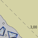
The illustrations in Fig.43 present the easy covering of dimensions which are object of the standards or customer requirements. For example, for the resin patterns in nominal dimension range from 3150 mm up to 4000 mm for the quality category K2 of EN 12890:2000, the permissible dimensional deviation is -3.2 mm. This situation is shown with the help of appropriate pictures from Figs.39-41, but the given start level is 3.0 mm.
The visualization includes as well pictures with fillers in different relations to the resin. Some moments from the wear of resin patterns which contain sand filler in relation of 1:1 to the epoxy resin (compound 29, Table 1) are presented in Fig.44.
An example for the start surface state of the resin patterns made by the conventional technology in plastic moulds is shown in Fig.45. The illustrations present the more roughness working surface than the smooth surface of the patterns from the vacuum-sealed sand moulds. Besides, the situation from Fig.38-d is taken into account from where the more quantity of microbubbles on the surface of samples from plastic moulds is visible.
In using of a filler which contains different grain fractions, an appropriate scheme is shown in Fig.46. There the sand filler consist of two predominant grain fractions 0.10 mm (~46%) and 0.063 mm (~24 %), in relation 2.5:1 to the epoxy resin.
The presented illustrations permit the realization of a variety of other intermediate images and working out of the appropriate computer simulations for the process of the resin patterns wear. « « « previous page next page » » » |